Building a Hypex UcD700-based power amp
Soft start circuits are something I should definitely have paid more attention to early on in the project. I rather naively
thought that the Hypex soft start module would be just fine:
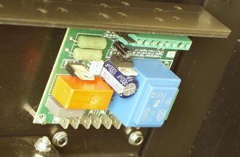
In fact it did work - if it was only powering-up the transformer without the smoothing caps connected. With the caps connected, it also worked. Once. On switching on the complete power supply for the very first time (from about six feet away and with suitable protective clothing and crash helmet, in case I'd wired the smoothing capacitors incorrectly), there were no dramas, no bangs or explosions. It just switched on, + & - 85V and probably enough energy to power the whole street for six months. I was amazed.
The second switch-on wasn't quite as drama-free. The soft start resistors started smoking quite badly... Better not try it a third time, I thought.
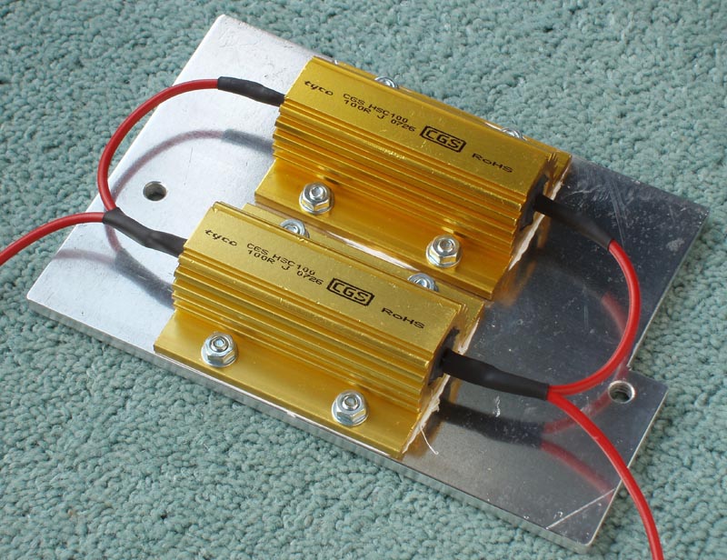
The resistors on the Hypex soft start were a couple of 5W wirewound in series, total resistance about 66R. Still being quite naive at this point I just replaced them with some bigger, off-board ones: two 100R, 100W ones in parallel:
On the third switch-on attempt I think the relay contacts welded themselves together so I now had a 'start' circuit without any 'soft' part. All subsequent attempts, of course, just kept blowing fuses (actually, some of them exploded). The resistors were, not surprisingly, fine.
It was at this stage that I thought I'd better do a bit more reading-up on softstarts. The Hypex soft starts are actually very sophisticated: zero-crossing triac switching, choice of latching and non-latching on-off switches, ability to drive bi-colour leds, and connection for a temparature sensor. It's just that they're probably a bit weedy when connected to a 2000VA transformer and 264,000uf of capacitors.
After lots of reading, mainly on diyaudio.com and Rod Elliot's excellent site I think I started to understand some of the problems. There seems to be two things going on here: the surge caused by switching on a big transformer, and the massive inrush of a large capacitor bank. The impact of the former seems to be related to where on the mains cycle you happen to be when the tranny is connected. I believe this is why zero-crossing techniques are often used for soft starts (like the Hypex one). After this initial switch on, the problem has passed so the delay-time (the time that the resistors are in circuit) can be very short - fractions of a second.
The second issue is the inrush caused by the capacitor bank, which initially, looks like a short-circuit. Most amplifiers don't have anywhere near as much capacitance as this one does, so a module like the Hypex one probably works fine. However in this case, after the fraction-of-a-second delay, the cap bank has barely started charging so as soon as the bypass relay closes, we get a massive current draw which is probably what welded the relay contacts together and blew all those fuses.
There seemed to be oposing schools of thought on using a long delay time (i.e. seconds) some reckoned this is a 'bad thing' for the transformer and suggested using a second soft start on the transformer secondaries. Others, oblivious to whether it's a bad thing or not, seemed to be happily using delays of several seconds without any apparent ill-effect. Of course, delay time can be reduced by allowing a larger current to be drawn during the 'soft' phase, i.e. lower value resistor, but we would still be talking about a long delay (seconds) for so much capacitance.
There were also other choices to be made about what to use for the 'resistor' part, many people using thermistors designed for this job. Lastly, it was clear from pretty much everybody that a big fear was what happens if the bypass relay failed to operate, leaving the resistors in circuit. The optimistic outcome (or hope) was that the resistors would fail by going open-circuit, cutting off the mains and not catching fire...
After consideration of the above, my own limited design knowledge and the ever important need for reliability, I designed my own soft start circuit. This was based around the same timer circuit I have been using for years in pre-amp power supplies to avoid switch on thumps, switching on (valve) heater supplies, etc. The circuit is an application note by Ray Marston from the April 1980 issue of ETI:
Time delay is set by R1 x C1. Although it's probably more complex than it needs to be, it works and it's very reliable having proven itself in my previous pre-amp PSU for the past 20 years.
At this point I also stumbled across Mark Hennessy's website, where he had solved the 'big fear' issue of what happens if the bypass relay fails by a really simple (and neat) arrangement of relay and resistors. It looks so obvious that it's a wonder why it isn't used more often, but I guess the best ideas are always the simple ones. It may not mitigate against a failure within the relay itself, but now if any of the control circuitry fails, the mains just gets disconnected. This goes a long way to making the circuit a lot more 'fail-safe'.
Mark also used a pic controller to control the relays, something that, again, I have no knowledge of. So, it's a case of using what I know, which is the above timing circuit, lots of (bigish) capacitors, big resistors and big relays. Boy, is it going to be un-sophisticated! The 'strowger exchange' of soft starts, perhaps...
First up, some breadboarding. I now needed to use the basic timing circuit to do a lot more work:
- connect power to the amp via the resistors
- after a few seconds delay, connect power directly to the amp
- disconnect the resistors (not essential, but desirable)
- operate a bi-colour led
- operate the UcD700's standby mode
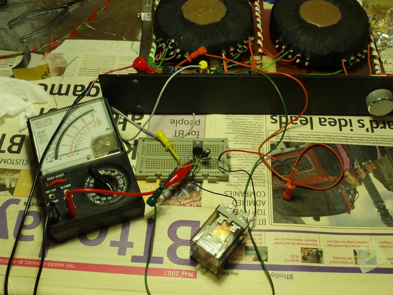
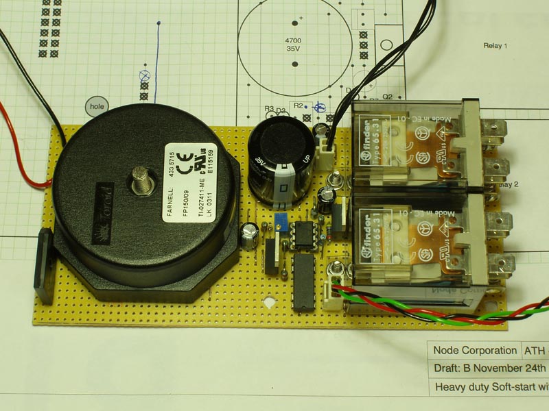
This is the aforementioned 20 year-old PSU with a few extra bits tacked-on. The 30A relay in the foreground will be the one that switches the resistors into circuit. As hoped, it comes on when power is applied and turns off just after the second relay (in this case, just visible within the PSU) switches on.
This is the final design I ended-up with for the soft start circuit:
As already mentioned, it's quite crude as it uses lots of relays - even for operating the Led and the amp module's mute/unmute. On switch-on (SW1 closed) RL1 immediately fires up and brings the big resistors into circuit and powers-up the amp. After the specified delay (determined by R2), the output of IC1 flips and relays 2, 3 and 4 fire up. RL2 bypasses the resistors and supplies power directly to the amp. RL3 just changes the Led from red to green. RL4 unmutes the amp module. At the same time, RL1 deactivates but takes a fraction of a second before doing so (due to the size of C3). This ensures that the resistors are switched-out of circuit and the slight delay ensures a smooth handover (overlap) with RL2. Using Mark Hennessy's arrangement of the power relays and big resistors means that in the event of a control circuit failure or if a relay fails to operate, power gets disconnected from the amp/resistors. The pdf version [650Kb] also has the component values for this circuit.
For the circuit board I reverted to veroboard. Again, many of the components are over-rated, or conservatively specced, I like to say. It probably is over the top to use a 11VA transformer and 4700uf smoothing cap, but I wanted a healthy margin on top of worst case conditions (in case all relays remain on). Darlington power transistors to operate the two 30A relays were chosen for similar reasons.
Compared with the original Hypex soft start, you can see it takes up quite a bit more room. Note that the only mains present on the veroboard is that to supply the transformer and is confined to the top-left of the board. All the heavy-duty mains wiring is made direct to the relay contacts.
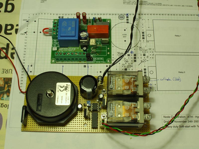
Since this photo was taken, the module has been slightly modified. For some reason, the resistor-relay which, on the breadboard didn't switch-off until a fraction of a second after the main relay kicked in, lacked this slight delay, here. This meant that there was the possibility of power to the amp being disrupted for a fraction of a second during the switchover between the two relays. To get round this, I just shunted the relay coil with lots of capacitance. Extremely crude, but it seemed to work! (the circuit diagram & pdf have been updated to take account of this).
Other than that, the circuit seems to work well. Currently the delay is approx four seconds (it's adjustable) and nothing seems to be objecting or has blown-up. In fact, compared with my own and other power amps (mine uses 2 x 700VA trannys), switching on so much latent (kinetic? potential?) energy has never been so undramatic. There are no buzzes, whines, hums, melting resistors or dimming lights. In fact, there is no noise at all, everything seems happy. Even though I'm using such a long delay, the capacitor bank has only reached 140V after four seconds. This is with 2 x 68R, 100W resistors in parallel. Incidentally, to discharge the cap bank I found the most convenient thing to use was a normal 60W lightbulb.
One last, but obvious, note: The mains is highly dangerous - if you're building anything mains powered, make sure you know exactly what you're dealing with. If not don't do it, or get someone who does know what they're doing!