Building a power supply for an Exposure VII pre-amp
Arguably pre-amp psus don't need an on-off switch as they tend to be left on 24/7, or if they do have a switch
a simple heavy duty rocker switch mounted on the back would usually sufice. In this case, a front mounted switch was
requested as the rack it was going to be housed in has relatively poor access to the back of the unit. However,
in order to retain some decency in the looks dept. a HD rocker switch doesn't really cut it. As mentioned earlier
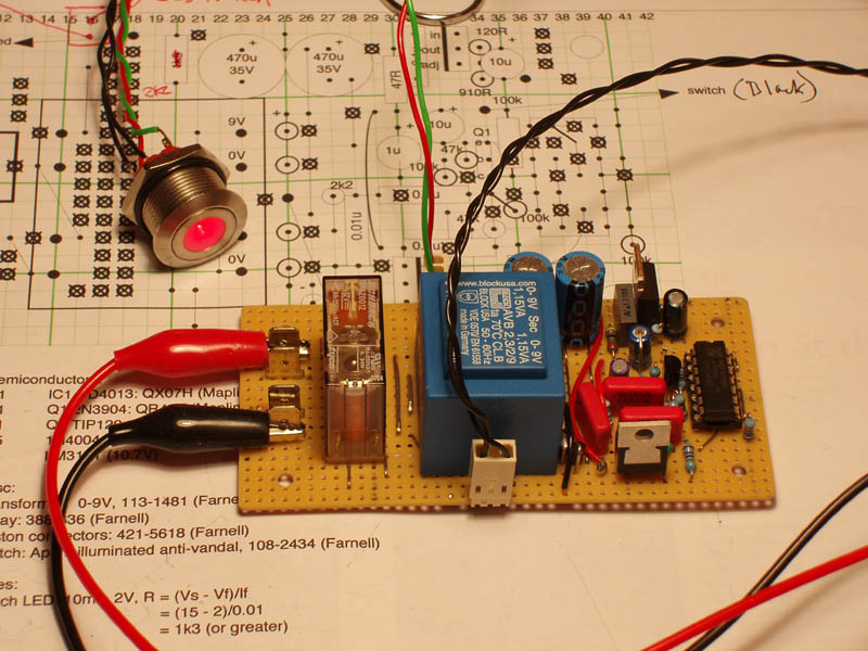
I came across a range of vandal-resistant push-button switches while perusing the usual RS/Farnell/Maplin catalogues
and, although pricey, would look a lot nicer. The switch in question was made by Apem (Farnell part no.:108-2434).
One issue with these switches is that they are non-latching so need a piece of flip-flop circuitry to provide the requisite on/off toggle action. A slight problem here is that I had never learnt or built anything to do with logic circuitry so it was very much a case of finding something 'off the shelf' and hope it's been reasonably well thought through.
The first port of call were my back-issues of ETI (Electronics Today International) where I came across a very simple flip-flop circuit by Ray Marston dating back to 1980. Unfortunately, it didn't work properly - it 'flipped' but didn't 'flop' as it were and I was really none-the-wiser for why this was the case - in my experience, stuff by Ray Marston always worked. On discussing this with a friend, he cheerfully pointed out that "logic has changed since 1980!" and that building old circuits with new chips didn't always work. I don't know how true that is but it sounded good!
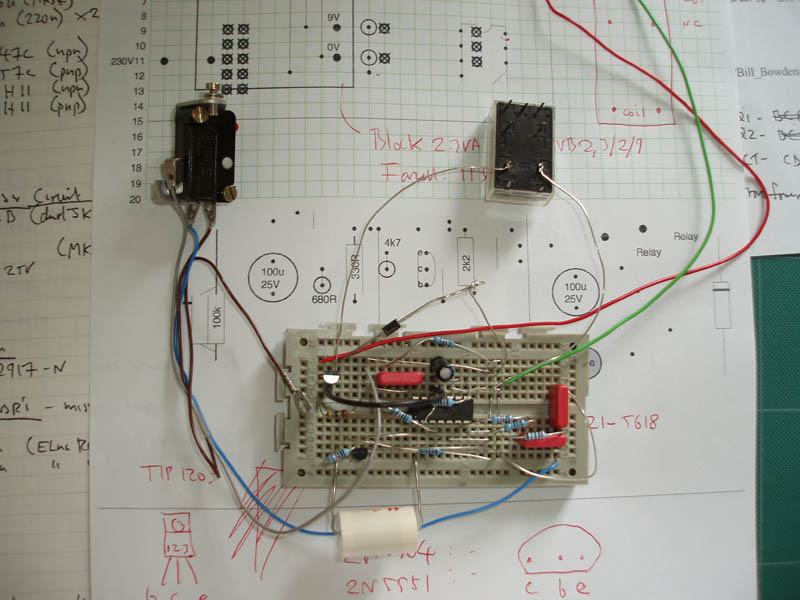
A trawl of the Internet threw up a circuit that did work, from a chap called Bill Bowden. The description shows that it's been very well thought through to make it real-world reliable. Incidentally, there are lots of useful circuits of all kinds on Bill's pages - well worth a look.
As mentioned, logic is all new teritory for me so it seemed prudent to breadboard the circuit first. The only thing I really changed was to use a massively overated relay drive transistor (a Tip120) to maximise reliability given that the circuit will be on most of the time:
One issue with these switches is that they are non-latching so need a piece of flip-flop circuitry to provide the requisite on/off toggle action. A slight problem here is that I had never learnt or built anything to do with logic circuitry so it was very much a case of finding something 'off the shelf' and hope it's been reasonably well thought through.
The first port of call were my back-issues of ETI (Electronics Today International) where I came across a very simple flip-flop circuit by Ray Marston dating back to 1980. Unfortunately, it didn't work properly - it 'flipped' but didn't 'flop' as it were and I was really none-the-wiser for why this was the case - in my experience, stuff by Ray Marston always worked. On discussing this with a friend, he cheerfully pointed out that "logic has changed since 1980!" and that building old circuits with new chips didn't always work. I don't know how true that is but it sounded good!
A trawl of the Internet threw up a circuit that did work, from a chap called Bill Bowden. The description shows that it's been very well thought through to make it real-world reliable. Incidentally, there are lots of useful circuits of all kinds on Bill's pages - well worth a look.
As mentioned, logic is all new teritory for me so it seemed prudent to breadboard the circuit first. The only thing I really changed was to use a massively overated relay drive transistor (a Tip120) to maximise reliability given that the circuit will be on most of the time:
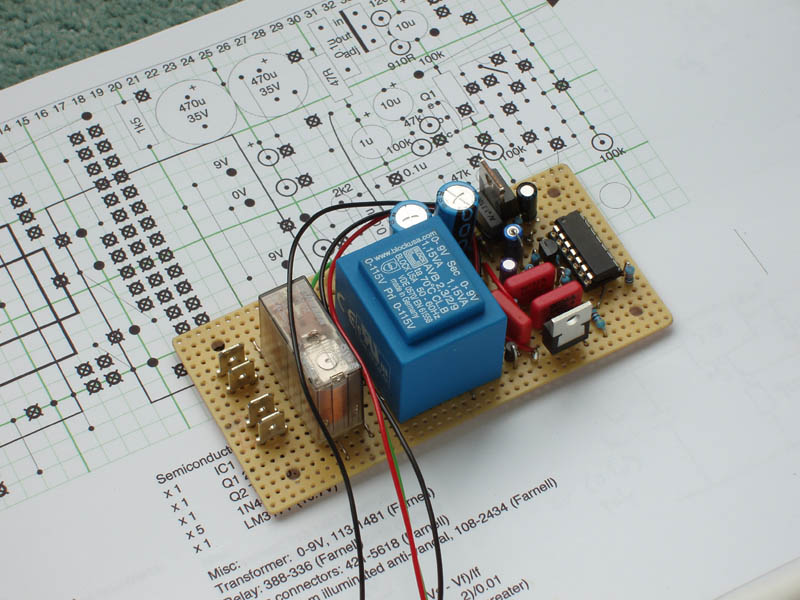
Luckily, this circuit worked perfectly so was transfered to a piece of veroboard. I know a pcb would look nicer, but again, I don't have that much experience designing PCBs. The veroboard doesn't look too bad imo. Underneath, the mains carrying parts that feed the psu-proper have been beefed up with silver-plated copper wire: