Building an 'XPS' power supply for a Naim CDS3
Finding out the voltages output by the XPS was made considerably more straightforward by reference to the excellent Pink Fish Media forum, where you'll find lots of threads
on diy XPS builds. A thread started by Teddy Pardo provided the answers:
The Naim XPS psu supplies four sets of voltages to the CD player:
1. + 15v (digital feed: CD drive control circuits, panel lights, etc)
2. + 15v (digital feed: clock, servo processor, etc)
3. ± 10v (two dacs (digital and analogue supply of the dacs))
4. ± 22v (analogue feed: op amps, I/V converter and filters)
From reference to info from Pink Fish and also pictures (e.g. from Acoustica another excellent site) it's possible to make a few observations about the Naim XPS. It uses a custom torroidal transformer feeding a total of 6 BHC pcb mount electrolytics (quite possibly ALP22 series in older units and maybe something from the ALC range for newer units?) into simple (but carefully selected/measured) 317/337 regulators. You can also just about see what looks like larger capacitors for the two single 15V rails (the two caps and regs towards the back of the unit). A quick flick through Farnell suggests that if theyre 40V, the smaller ones could be something like 10,000uf (35 dia by 45 high) and the larger could be 22,000uf (40 dia by 55 high)?
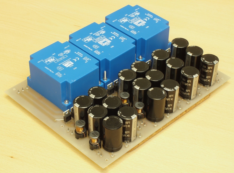
For my DIY version, Ive used Nipon Chemi-con SMH capacitors of 6800uf @ 50V. The main reason being that LesW uses the 100V versions in his Cap6 capacitor bank. And I also managed to buy a job-lot of 60 of these from ebay some time ago for a very attractive price! The idea is to emulate something like an Avondale Cap6 and use a C-L-C-L-C configuration, i.e. a cap input filter (as opposed to a choke input filter). For inductors, many pink fishers seem to be using around 10uH air-cored hand wound items (see this thread). To save a bit of effort I used some off-the-shelf Panasonic ferrite cored inductors from RS. I don't know if the fact that they're not air-cored will have a detrimental effect, but hopefully their 6.5A rating will help ameliorate this.
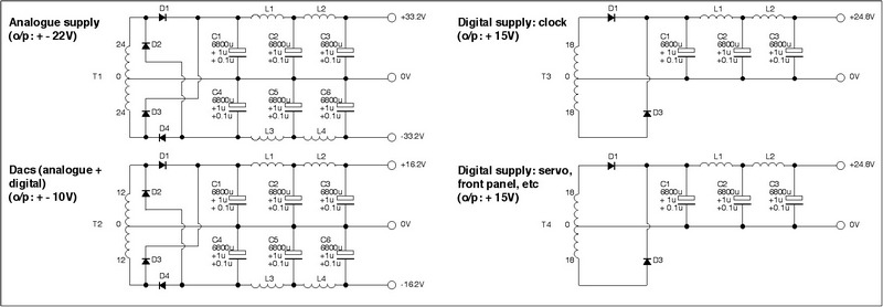
The circuit diagram of the raw supply I used is shown below. For the first time in any of my psu projects, I thought I'd try the (popular amongst the DIY community) MBR20200CTG Schottkys for the rectifers. I've also uploaded a pdf version of this circuit [61Kb]. Note that both show bypass capacitors for the main reservoir caps. These didn't actually make it into build as I couldn't actually find room for them on the limited size of the pcb board (so much for no-compromise, eh!).
The Naim XPS psu supplies four sets of voltages to the CD player:
1. + 15v (digital feed: CD drive control circuits, panel lights, etc)
2. + 15v (digital feed: clock, servo processor, etc)
3. ± 10v (two dacs (digital and analogue supply of the dacs))
4. ± 22v (analogue feed: op amps, I/V converter and filters)
From reference to info from Pink Fish and also pictures (e.g. from Acoustica another excellent site) it's possible to make a few observations about the Naim XPS. It uses a custom torroidal transformer feeding a total of 6 BHC pcb mount electrolytics (quite possibly ALP22 series in older units and maybe something from the ALC range for newer units?) into simple (but carefully selected/measured) 317/337 regulators. You can also just about see what looks like larger capacitors for the two single 15V rails (the two caps and regs towards the back of the unit). A quick flick through Farnell suggests that if theyre 40V, the smaller ones could be something like 10,000uf (35 dia by 45 high) and the larger could be 22,000uf (40 dia by 55 high)?
For my DIY version, Ive used Nipon Chemi-con SMH capacitors of 6800uf @ 50V. The main reason being that LesW uses the 100V versions in his Cap6 capacitor bank. And I also managed to buy a job-lot of 60 of these from ebay some time ago for a very attractive price! The idea is to emulate something like an Avondale Cap6 and use a C-L-C-L-C configuration, i.e. a cap input filter (as opposed to a choke input filter). For inductors, many pink fishers seem to be using around 10uH air-cored hand wound items (see this thread). To save a bit of effort I used some off-the-shelf Panasonic ferrite cored inductors from RS. I don't know if the fact that they're not air-cored will have a detrimental effect, but hopefully their 6.5A rating will help ameliorate this.
The circuit diagram of the raw supply I used is shown below. For the first time in any of my psu projects, I thought I'd try the (popular amongst the DIY community) MBR20200CTG Schottkys for the rectifers. I've also uploaded a pdf version of this circuit [61Kb]. Note that both show bypass capacitors for the main reservoir caps. These didn't actually make it into build as I couldn't actually find room for them on the limited size of the pcb board (so much for no-compromise, eh!).
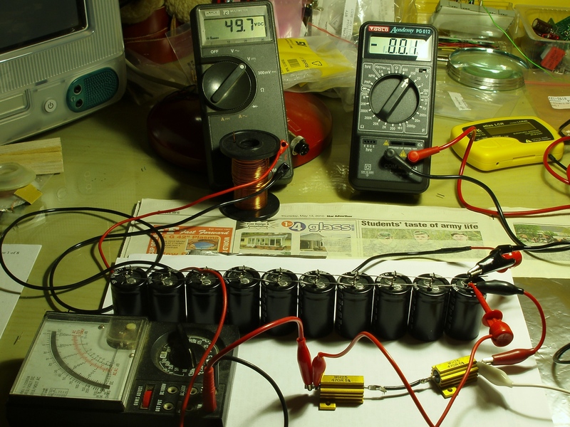
Although they're unlikely to be more than 10 years old, I still don't know how long the SMH capacitors had been hanging around before I bought them (and I've had them for a couple of years), it seemed sensible to 'reform' them to make sure they work ok and don't blow-up on power-up! There are many articles on the net about how to do this - here's one, and here's another.
The picture below shows 10 of the capacitors being reformed. They're rated at 50V and as you can see I've taken them pretty much up to their maximum. This was done gradually starting with lower voltages and taking place over several days. Hopefully, I've ended up with a bunch of sensible, well- behaved capacitors :-)
The choice of transformers could have gone in a number of directions: Specify a custom wound item from, say, Avondale Audio or Canterbury windings. Or keep an eye on the budget and use some off-the shelf items. Or use four of LesW's (Avondale) special laminated transformers. Although I have a number of LesW transformers, they're all 25-0-25 so although I could have used four of these, the power dissipation for the 10V and 15V supplies would have been higher than I would have liked. In the end I chose a compromise - using one of LesW's for the analogue supply and three general purpose Block 52VA pcb-mounting laminated transformers for the remaining three supplies (RS nos.: 201-7599 and 201-7561). Will the latter compromise the performance? Who knows!
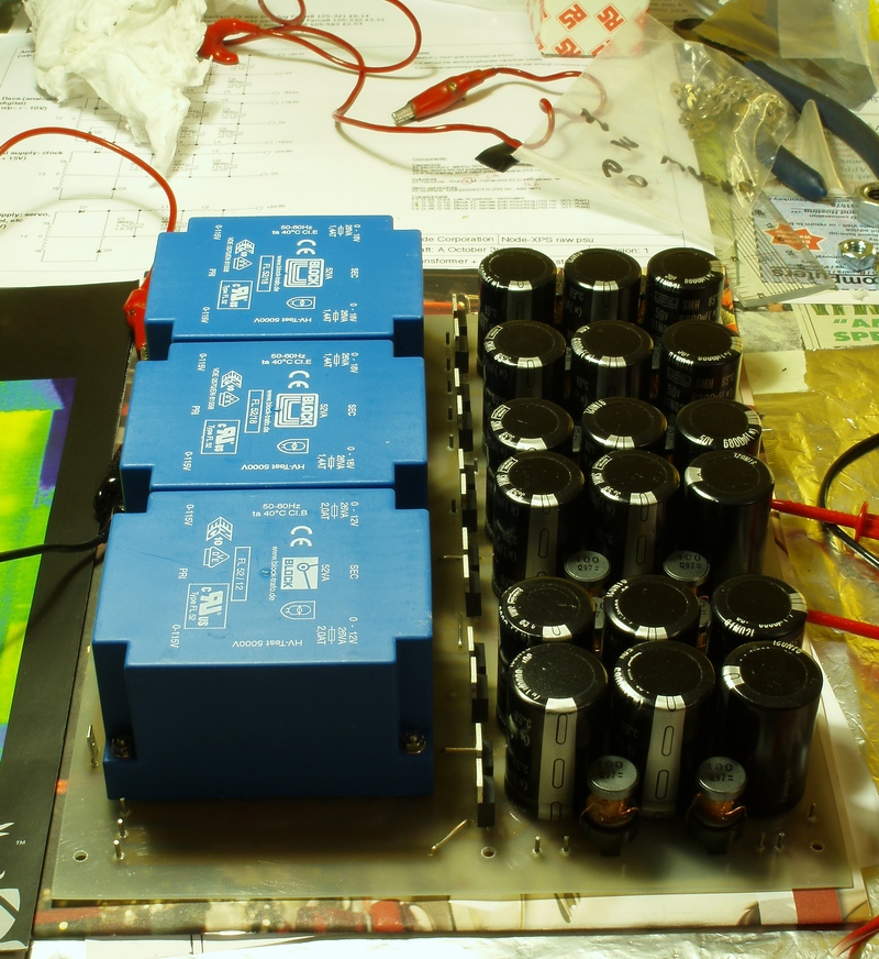
Here's another picture of the assembled raw power supply board: