Building an 'XPS' power supply for a Naim CDS3
For the Burndy lead my first thought was to pick one up from ebay, but there was nothing available when I happened to be looking,
at least not at a 'sensible' price! I believe a brand new lead from Naim will set you back £395 (which is probably more than it's cost me
to build this entire psu) so more DIY was the obvious option.
Information on various Pink Fish threads tell us which plug pins carry which voltages. Here are just a couple:
burndy pin layout for XPS2
Naim CD555 PSU burndy pin layout
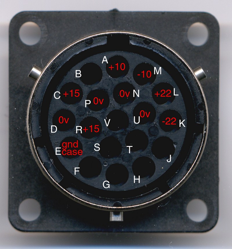
Translating this to the power socket, my understanding is that it looks like this:
The actual connectors can be had from Farnell or RS:
Farnell:
FCI metalock bantam 19 way pin plug Farnell 105-321
FCI metalock bantam 19 way panel socket Farnell 105-330
FCI metalock bantam AC basic hood Farnell 105-583
3652051 25 CRIMP SOCKET, 20-16AWG
3652026 25 CRIMP PIN, 20-16AWG
RS:
SOURIAU 19w metalok bantam chassis skt: 220-2876
Crimp machined socket contact,18-16awg: 273-2901
I've no idea what's in the Naim Burndy lead, whether it's screened or contains any 'special' ingredients. For my version I just wanted to make sure it had reasonably low impedance.
Information on various Pink Fish threads tell us which plug pins carry which voltages. Here are just a couple:
burndy pin layout for XPS2
Naim CD555 PSU burndy pin layout
Translating this to the power socket, my understanding is that it looks like this:
But which 0v connections match to which rail voltages?
Again, this thread seems to have the answers:
burndy pin layout for XPS2
Extract (from 'bobo'):
----------------------------
CP (15, 0): power for motors
RD (15, 0): power for digital (eeprom, DAC and current/voltage converting opamps are all on the ground plane fed by D/E2)
ANM (10, 0, -10): low power analog (and C/V convertors?)
LUK (22, 0, -22): high power and low noise output
E(0): GND mekka, directly connected to analog 0. Perhaps the (dirty) digital and motor grounds (D and P) connect via a small isolation-coils. I couldn't see any of those on the board though.
----------------------------
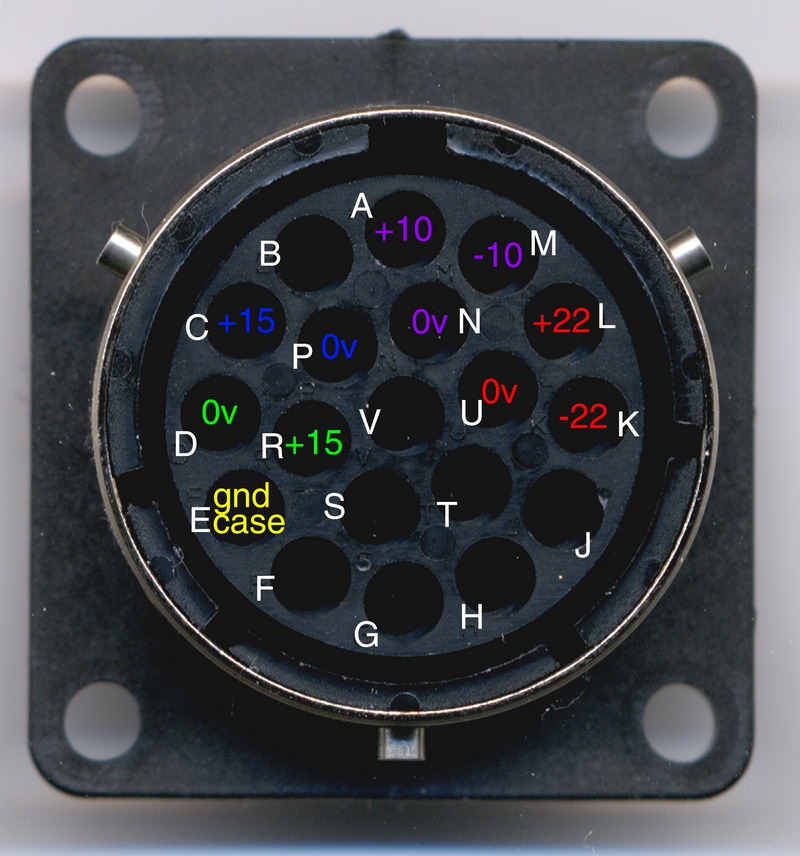
I'm not sure about pin E connecting to any of the other 0v points, so I've connected it to the case metalwork and mains earth only. So, I now have this:
Again, this thread seems to have the answers:
burndy pin layout for XPS2
Extract (from 'bobo'):
----------------------------
CP (15, 0): power for motors
RD (15, 0): power for digital (eeprom, DAC and current/voltage converting opamps are all on the ground plane fed by D/E2)
ANM (10, 0, -10): low power analog (and C/V convertors?)
LUK (22, 0, -22): high power and low noise output
E(0): GND mekka, directly connected to analog 0. Perhaps the (dirty) digital and motor grounds (D and P) connect via a small isolation-coils. I couldn't see any of those on the board though.
----------------------------
I'm not sure about pin E connecting to any of the other 0v points, so I've connected it to the case metalwork and mains earth only. So, I now have this:
The actual connectors can be had from Farnell or RS:
Farnell:
FCI metalock bantam 19 way pin plug Farnell 105-321
FCI metalock bantam 19 way panel socket Farnell 105-330
FCI metalock bantam AC basic hood Farnell 105-583
3652051 25 CRIMP SOCKET, 20-16AWG
3652026 25 CRIMP PIN, 20-16AWG
RS:
SOURIAU 19w metalok bantam chassis skt: 220-2876
Crimp machined socket contact,18-16awg: 273-2901
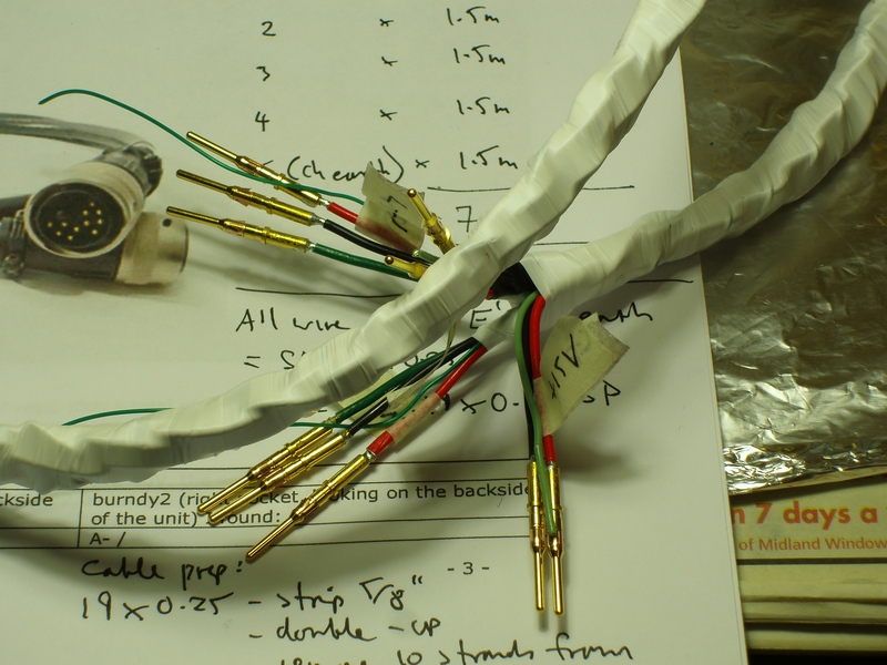
I've no idea what's in the Naim Burndy lead, whether it's screened or contains any 'special' ingredients. For my version I just wanted to make sure it had reasonably low impedance.

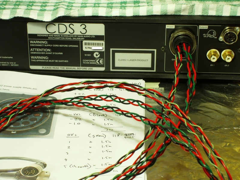
It consists of four bundles of wires, each wire of 19/0.25 silver-plated construction. This hopefully keeps the bulk down but still having lowish impedance - the wire has a current rating of 15A, yet a CSA of only 0.933 mm2.
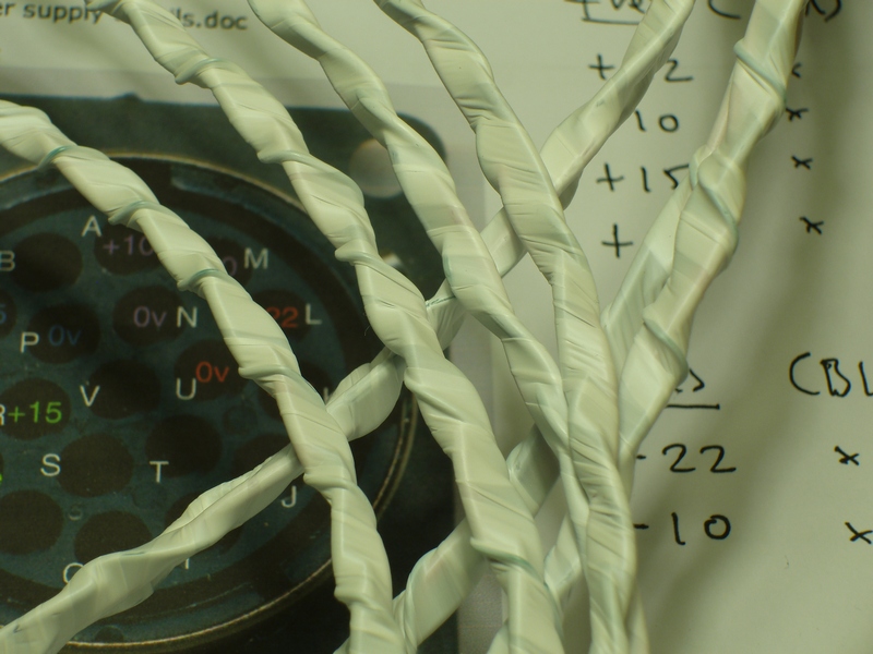
Each bundle is plaited together and then wrapped in ptfe (plumbers) tape to hold it together:
And then all four bundles are wrapped overall in ptfe before finished with an expanding braided sleeving.
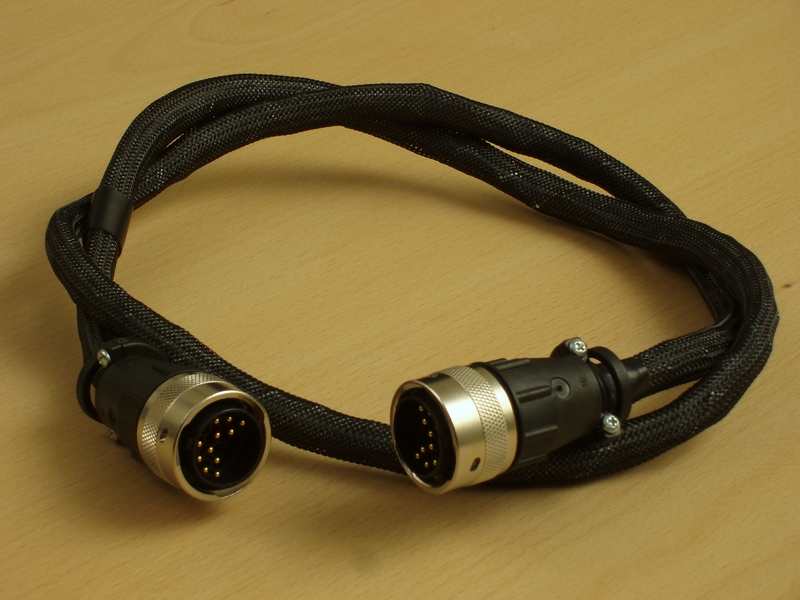
The final result is a bit stiff and a bit lumpy looking. If I was making another I might forego the overall wrap of ptfe tape to make it more
flexible. Of course this might make it even lumpier! However, as it is, it seems to get the job done.