Building an 'XPS' power supply for a Naim CDS3
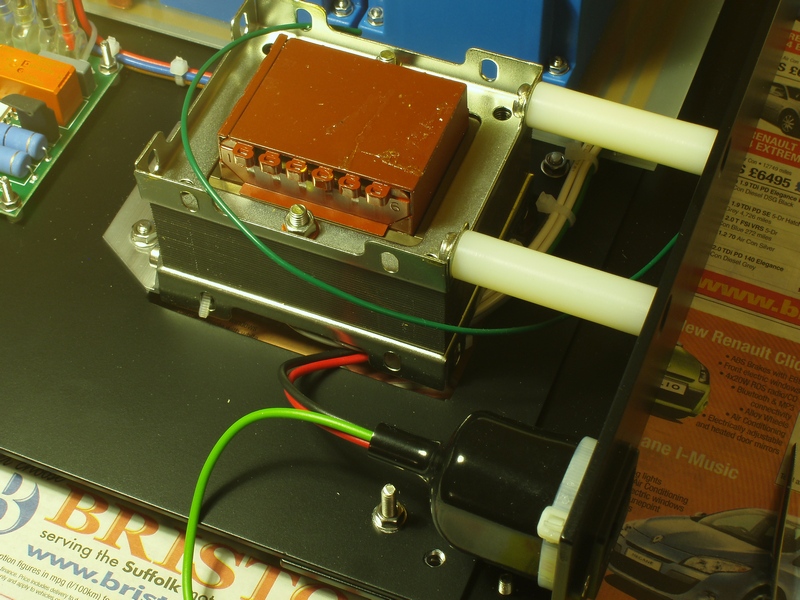
Transformer and soft-start:
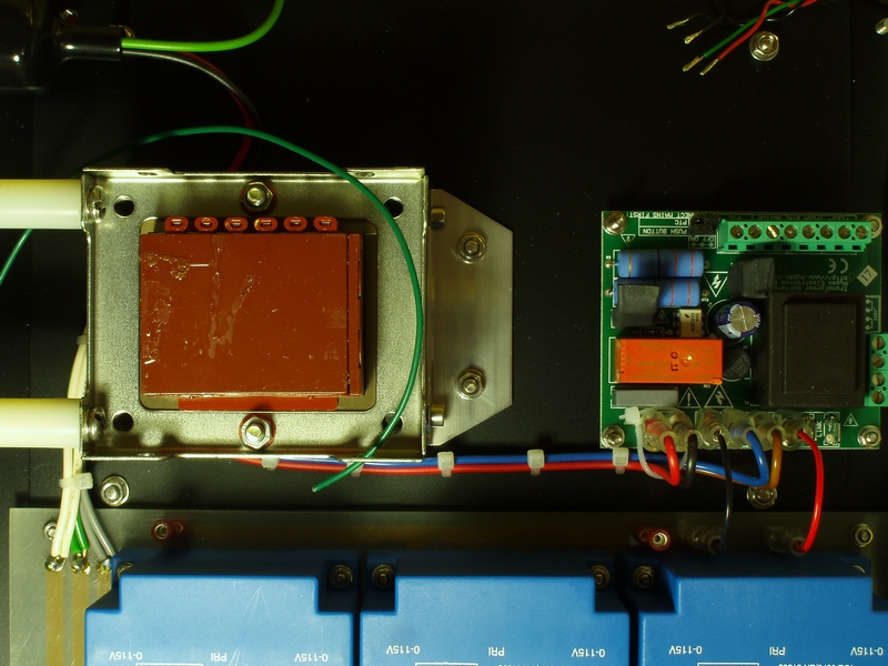
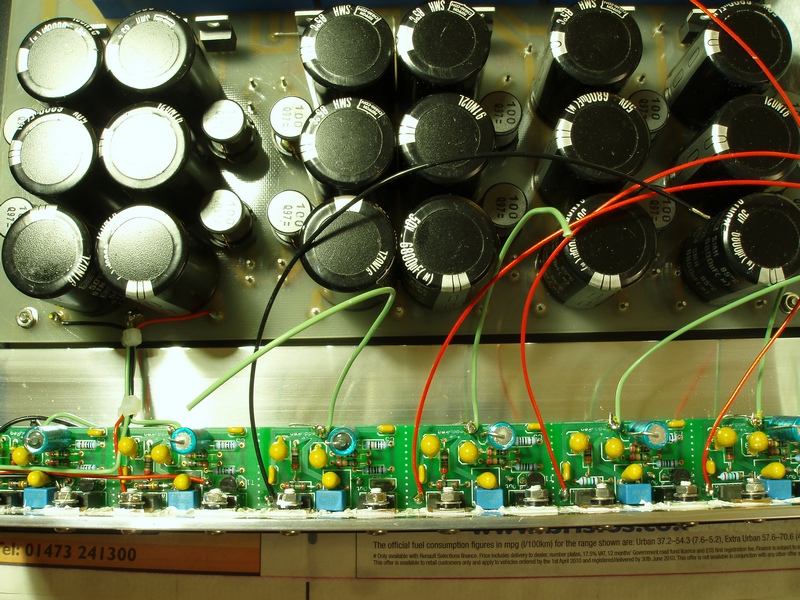
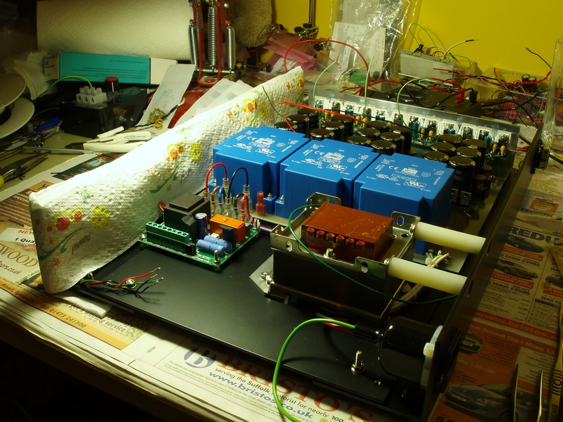
Picture of the regulator board. The Naim psu uses the basic LM317/337 application circuit, as used in many of their psus. Performance is critically determined by what looks like very careful component selection/matching, along with very large smoothing capacitors and transformers. I think I remember reading on the Naim forum some years ago that they reject the majority of regulators they buy in. I imagine that those that 'make the cut' are graded so that the best get used in the expensive stuff, with the 'only-just-in-tolerance' ones ending up in FlatCaps. In this way, it looks like a very simple circuit is made to perform to a higher-than-expected standard.
Given that the CDS3 itself contains several more 317/337 regulators, one school of thought suggests that it may be of limited value putting too much
sophistication into the power supply regulators. For this diy build, the 'standard' TeddyReg pretty much chose itself. Why? Well because
they're relatively inexpensive and I already had a number of TeddyReg pcbs from an earlier Pink Fish group buy!
General details of the regulator can be found on Pink Fish, Acosutica and also, of course, on Teddy Pardo's site. It would have been interesting to try Teddy's SuperTeddyReg or some VBE'd ALW super regulators, but this would have added quite a bit more to the overall costs (hey, there's a recession on, you know...)
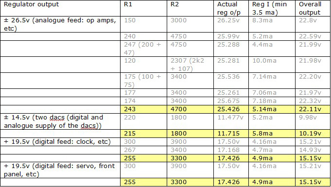
Bearing in mind the voltage drop across the Vbe, resistor values for the LM317/337 section were worked out thus:
Voltage calculations for a bare 317/337: Vout = 1.25 (1 + (R2/R1))
However, the Vbe soaks up approx 4.5V so in the above values (for a 25V output), the actual voltage needs to be set higher - 29.6v in this case.
For the Vbe: Vout = (Regout x R4) / (R3 + R4)
Therefore our outputs become:
General details of the regulator can be found on Pink Fish, Acosutica and also, of course, on Teddy Pardo's site. It would have been interesting to try Teddy's SuperTeddyReg or some VBE'd ALW super regulators, but this would have added quite a bit more to the overall costs (hey, there's a recession on, you know...)
Bearing in mind the voltage drop across the Vbe, resistor values for the LM317/337 section were worked out thus:
Voltage calculations for a bare 317/337: Vout = 1.25 (1 + (R2/R1))
However, the Vbe soaks up approx 4.5V so in the above values (for a 25V output), the actual voltage needs to be set higher - 29.6v in this case.
For the Vbe: Vout = (Regout x R4) / (R3 + R4)
Therefore our outputs become:
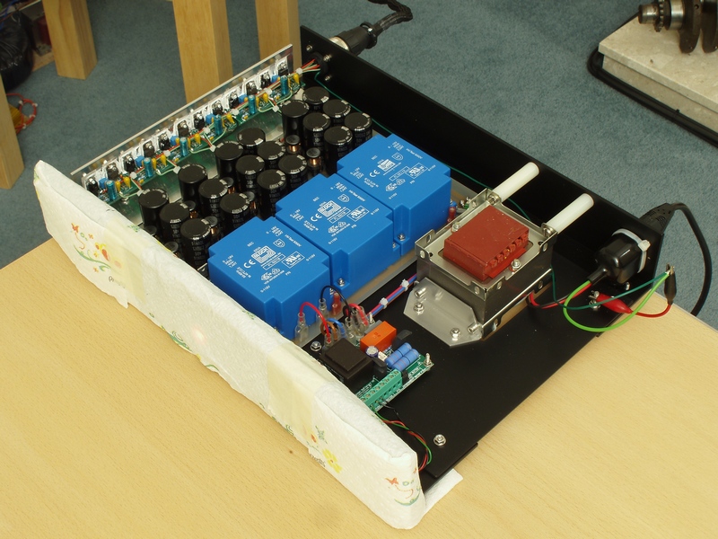
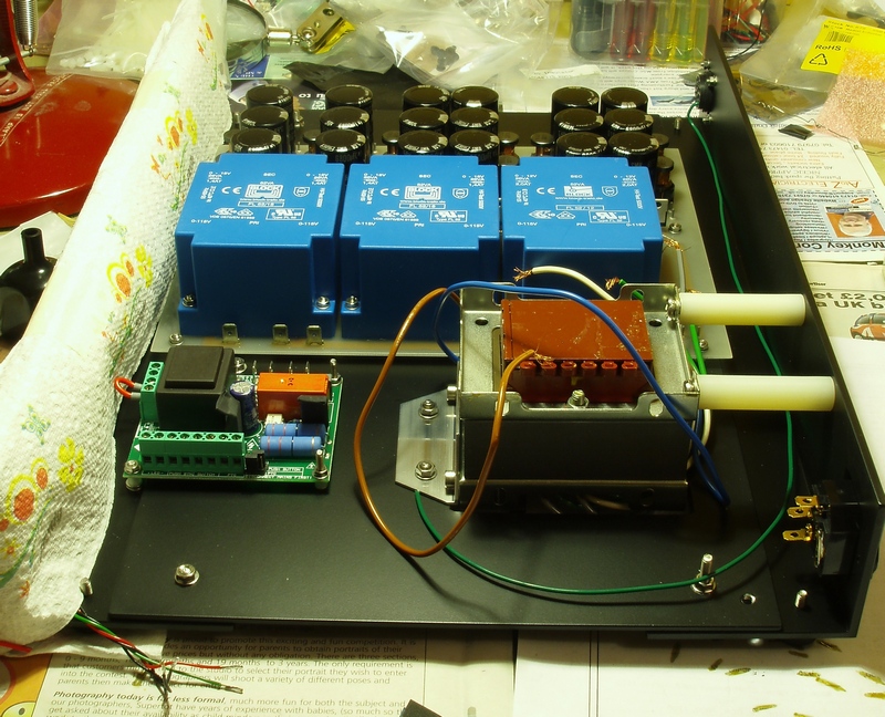
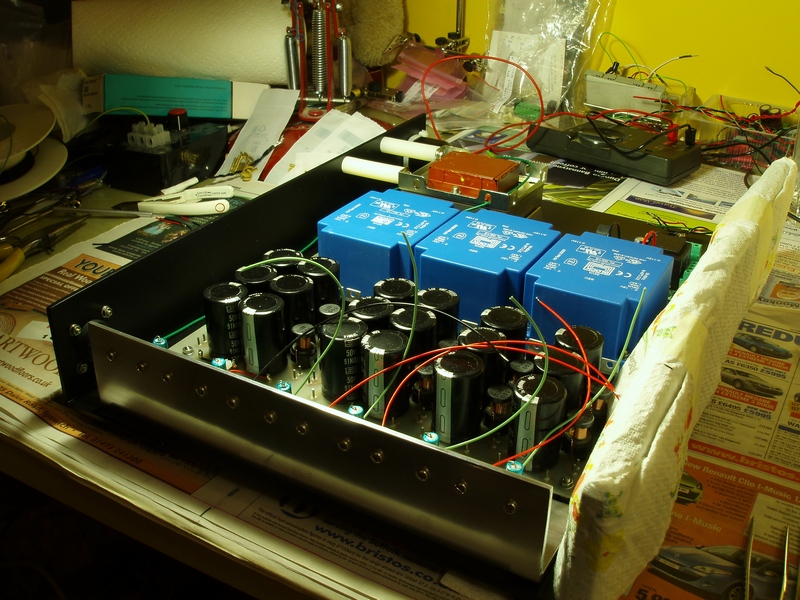
General shot of the unit from both sides:
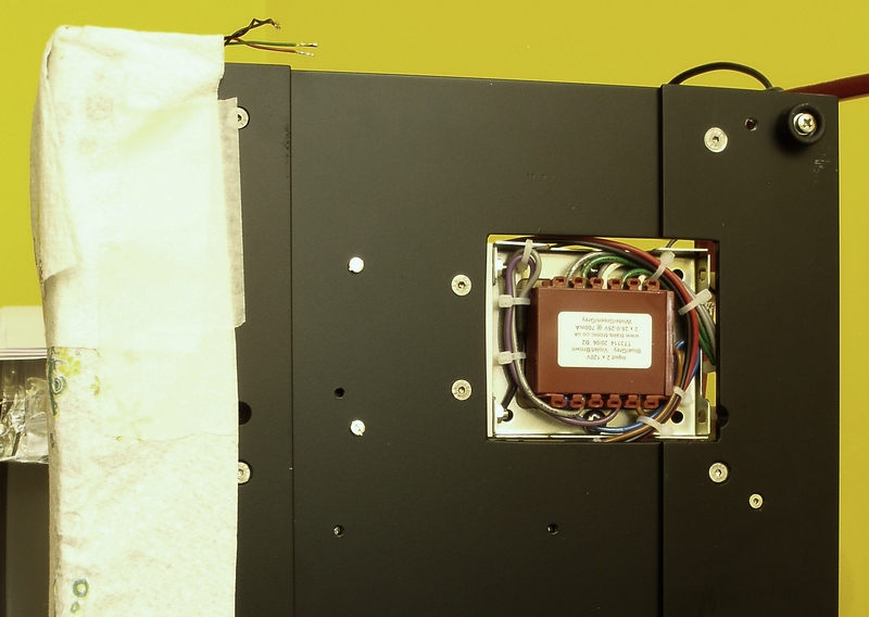
The slightly unusual mounting method for the transformer was simply due to having some 'Transipillars' (from Farnell) lying around. I know from when I used to use the smaller versions of these as structural parts in the chassis of radio-controlled race cars that they're pretty much indestructable, so using a couple of the bigger versions, here, should be no problem. This also provides a slot for the cables to emerge from underneath.
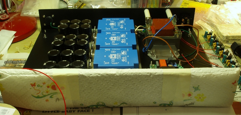
Picture of the almost complete unit: